Mostrando entradas con la etiqueta Tirso Ramírez. Mostrar todas las entradas

domingo, 14 de febrero de 2010

transmisor-FM


transmisor-FM
Griffin iTrip, ahora para el iPod Nano 4G

Escrito el Jueves, 19 de Febrero de 2009 a las 17:52 en Accesorios  |  autor: E. Serveto

Griffin iTrip

El pasado agosto ya comentamos el inventito de Griffin diseñado para emitir el audio de tus cacharros hasta la radio más cercana, el Griffin iTrip, y ahora la compañía ha decidido sacar una nueva versión, esta vez enfocada para el iPod Nano 4G.

La compañía, que suponemos que quiere aprovechar el filón antes de que todos los coches lleven soporte para reproductor MP3 (poco debe faltar), ha lanzado el nuevo Griffin iTrip para iPod Nano 4G (aunque funcionará con todas las versiones del Nano) con un acertado diseño redondeado, que hará que se acople perfectamente a la forma del reproductor.

Con él, podrás enviar tu colección musical desde el iPod hasta la radio del coche (si estás en el comedor déjate de radios y usa un cable RCA, por Dios), permitiéndote disfrutar de tu colección en la carretera. Además, la tecnología SmartScan del aparatito se encargará de rebuscar entre el espectro de frecuencias la mejor frecuencia abierta que pueda utilizar, guardándola para posteriores usos. A la venta por 30 libras, 34 euros al cambio de hoy.

Vía PocketLint.

Plug-in Car MP4 Player, PMP con transmisor FM de Chinavision
Escrito el Sábado, 3 de Enero de 2009 a las 18:00 en Reproductores  |  autor: Fabian

transmisor fm con reproducción de MP3 y MP4

La costumbre del todo en uno llega ahora de la mano de Chinavision con su nuevo producto, el Plug-in Car MP4 Player, un económico transmisor FM que integra un reproductor multimedia con pantalla a color de 1,5 pulgadas y 4 GB de memoria.

Lo normal es que todo el mundo tenga un reproductor de MP3 y el transmisor FM por separado. Sin embargo, el Plug-in Car MP4 Player combina estos dos elementos más la reproducción de ví­deo MP4, y por tanto lo podemos considerar como un PMP. Como hemos dicho, dispone de 4 GB de memoria interna, ranura para tarjetas SD y conexión USB para transferir archivos desde el ordenador.

A pesar de que en su  carcasa y nombre indica que es MP4, lo cierto es que sólo reproduce ficheros en formato AMV y por tanto necesitaremos un conversor para poder ver los ví­deos. Por otra parte, con sólo 1,5 pulgadas de pantalla y teniendo en cuenta que está pegado al encendedor del coche, vemos un poco difí­cil, además de peligroso, visualizar ví­deos en el coche, incluso para los acompañantes.

Seguir Leyendo: Plug-in Car MP4 Player, PMP con transmisor FM de Chinavision

iBreath Alcohol Breathalizer, alcoholímetro con transmisor FM para iPod y iPhone
Escrito el Lunes, 22 de Diciembre de 2008 a las 15:40 en Accesorios  |  autor: Fabian

iBreath Alcohol Breathalizer

En estas fechas navideñas cargadas de comilonas con la empresa, família y amigos, tenemos que ir con cuidado con el alcohol y la carretera. iBreath Alcohol Breathalizer es un alcoholímetro que se conecta al iPod o iPhone con funciones de transmisor FM.

Su funcionamiento es bastante simple y esperable. Lo conectamos a la base del iPod/iPhone, lo ponemos en modo alcoholímetro y soplamos durante unos cinco segundos hasta obtener los resultados de alcohol en sangre. Por otra parte, si seleccionamos la opción de transmisor FM podremos transferir nuestra música a cualquier receptor FM, como la radio del coche o cualquiera que tengamos por casa. También tiene funciones de reloj y alarma e incorpora cargador para el coche.

Su precio es de 80 dólares. Aunque suponemos que no está homologado, puede ser de gran ayuda para saber en qué estado nos encontramos antes de coger el coche. Los transmisores FM no son la mejor opción para escuchar la música de nuestro reproductor en otros dispositivos en cuanto a calidad de sonido e interferencias. Pero combinado con el alcoholímetro, al menos le podremos dar más utilidad y aprovechar esos 80 dólares.

Y recuerda, si bebes, no conduzcas.

Vía newlaunches.

Trekstor RadioStation f.ox, tu música en el coche
Escrito el Viernes, 14 de Noviembre de 2008 a las 08:00 en Accesorios  |  autor: Fabian

Radio-Statoin-fox

Si queremos escuchar la música de nuestros reproductores portátiles en el coche, Trekstor RadioStation f.ox es una solución factible y relativamente barata, siempre que no tengamos fundido el fusil del encendedor de nuestro vehículo o no necesitemos el mechero para fumar empedernidamente.

Trekstor RadioStation f.ox funciona realmente como un transmisor FM, del siguiente modo: conectamos nuestro reproductor portátil de música (MP3, iPod, CD, etc.) al dispositivo mediante su entrada de línea de 3,5 mm. Éste, que estará enchufado a la toma del encendedor, emitirá nuestra música hacia la antena del coche según la frecuencia que seleccionemos. Y,  finalmente, la radio del coche, que estará sintonizada a esa misma frecuencia, reproducirá nuestra música.

Además de los reproductores portátiles, también admite como fuente de audio una memoria flash USB, es decir, un pen-drive. Eso sí, los formatos han de ser MP3 o WMA. Es  de destacar, que el conector USB también nos permite cargar las baterías de todos aquellos reproductores MP3 que incluyen esta opción. El display del RadioStation f.ox es tan simple como un LED de siete segmentos, y nos recuerda a los relojes despertadores que muchos seguimos teniendo.

Seguir Leyendo: Trekstor RadioStation f.ox, tu música en el coche


Belkin TuneCast Auto, transmisor FM para el iPhone 3G
Escrito el Lunes, 4 de Agosto de 2008 a las 12:14 en Accesorios  |  autor: Jon Hdez

Belkin TuneCast Auto

Nunca me han gustado los transmisores FM como el Belkin TuneCast Auto que os traigo hoy. Donde esté un ochentero adaptador de cassette, que se quiten puertos USB, iGolfs y demás artilugios. Además, está más que comprobado que los transmisores FM son la peor de las alternativas al mí­tico adaptador.

Partiendo de que los transmisores FM tienen una potencia muy limitada para mantenerse dentro de la legalidad, que es más probable que Apple presente un iPod con radio que encontrar una frecuencia limpia en los centros urbanos, y que suelen ser bastante caros, no te puedes extrañar de que siga prefiriendo la antigua solución.

No obstante, parece que Belkin ha hecho los deberes, a medias. El Belkin TuneCast Auto, por los casi 60 euros que cuesta, se encargará automáticamente de buscar la mejor frecuencia FM para emitir (supongo que si entra en un bucle infinito, la garantí­a no lo cubre) y, mientras tanto, recargará la sufrida baterí­a del iPhone (o iPod) que tengas conectado con su cargador de mechero.

Seguir Leyendo: Belkin TuneCast Auto, transmisor FM para el iPhone 3G

Gear4 AirZone FM Dock, transmisores FM
Escrito el Jueves, 27 de Marzo de 2008 a las 17:18 en Audio Portatil  |  autor: Jon Hdez

Gear4 AirZone FM Dock

Los transmisores FM, como el Gear4 AirZone FM Dock que hoy nos ocupa, son una alternativa válida a los altavoces portátiles. No obstante, hay que tener en cuenta que la calidad del audio se degradará considerablemente y que su alcance está bastante limitado.

Dicho esto, la gran ventaja del Gear4 AirZone FM Dock es que no es tan aparatoso como otros transmisores FM que hemos visto por aquí­. De hecho, es tan pequeño que se alimenta directamente de la baterí­a del iPod, lo que repercutirás en una menor autonomí­a de tu reproductor y en la potencia de la señal que el propio transmisor FM puede desarrollar.

También viene provisto de un detalle esencial: una memoria para 4 sintoní­as. Así­, cuando consigas encontrar una frecuencia limpia -tarea bastante difí­cil en las grandes ciudades-, podrás guardarla y acceder a ella solamente pulsando un botón.

Seguir Leyendo: Gear4 AirZone FM Dock, transmisores FM

XtremeMac InCharge FM, transmisor FM para iPod
Escrito el Miércoles, 23 de Enero de 2008 a las 15:05 en Audio Portatil  |  autor: Willy Klew

xtrememacinchargefm

XtremeMac ha presentado un nuevo modelo de transmisor FM para iPod, el InCharge FM, que ofrece alta calidad de sonido gracias a la incorporación de la tecnologí­a PureFM de Quintic.

De acuerdo a XtremeMac, esta tecnologí­a ofrece una calidad de audio hasta ahora nunca lograda en dispositivos de este tipo, y está destinada a los más exigentes usuarios. Claro que además de transmitir la música de tu iPod, el Xtreme Mac InCharge FM también recarga la baterí­a del reproductor, de modo que estamos ante un práctico dispositivo multifunción.

Seguir Leyendo: XtremeMac InCharge FM, transmisor FM para iPod

Garmin renueva los Navegadores GPS Nuvi
Escrito el Viernes, 4 de Enero de 2008 a las 12:23 en GPS  |  autor: Jon Hdez

Garmin Nuvi 260w

Y con cuatro modelos, nada más y nada menos, que se unirán a los Garmin Colorado que os mostramos hace un rato. Los modelos responden a los nombres de Garmin Nuvi 260w, Garmin Nuvi 780, Garmin Nuvi 880 y Garmin Nuvi 5000. Pasamos a desglosarlos uno por uno.

El Garmin Nuvi 260w, actualización del Garmin Nuvi 260, viene con una pantalla panorámica táctil de 4,3 pulgadas que se puede usar a plena luz del dí­a. También destaca por los avisos vocales de los nombres de las calles donde debemos girar, así­ como por el sistema de seguridad Garmin Lock, que bloquea el navegador GPS con un código de 4 cifras. Si no lo introducimos, no funciona, aunque también podemos llevar el GPS a una localización segura, que habremos configurado anteriormente, y se desbloqueará automáticamente.

El apartado de extras, que también viene cargadito, completa lo más significativo de este navegador GPS y que cuenta con: visor de imágenes, calculadora, conversor de divisas y reloj mundial. No hay precio, ni fecha de lanzamiento todaví­a, pero en los próximos dí­as sabremos algo.

Seguir Leyendo: Garmin renueva los Navegadores GPS Nuvi

Transmisor FM para móviles Sony Ericsson
Escrito el Miércoles, 14 de Noviembre de 2007 a las 20:01 en Audio Portatil  |  autor: Ceritium

Transmisor FM Sony Ericsson

Con este transmisor FM podrás escuchar las canciones de tu Sony Ericsson fácilmente en la radio de tu coche o en la que más te plazca.

Hoy en día sigue siendo muy común que la gente tenga un móvil y a parte cuenten con un reproductor de MP3 portátil, como podría ser cualquier modelo de iPod o cualquier otro aparato, sin embargo ya son muchos los que usan su móvil como principal medio para reproducir audio portátil, sobre todo los usuarios de aquellos modelos que traen auriculares de serie.

Adaptadores para emitir FM seguro que hay alguno que otro más, de momento aquí te informamos de uno que además puedes adquirir en USBFever por solo 30$. Vía RedFerret
Por: Tirso Ramírez  C.I.: 18392099
CAF


Low-Level RF System Design for the Accelerator Test Facility (ATF) Damping Ring


Low-Level RF System Design for the Accelerator Test Facility (ATF) Damping Ring


M. Minty

LOW-LEVEL RF SYSTEM DESIGN FOR THE ACCELERATOR TEST FACILITY (ATF) DAMPING RING

M.G. Minty, SLAC, Stanford, CA 94309, USA K. Kubo, F. Hinode, S. Sakanaka, J. Urakawa, KEK, Oho, Tsukuba-shi, Ibaraki-ken, 305 Japan
Abstract
The ATF damping ring [1] was built to demonstrate the production of low emittance, high current beams for future linear colliders. To attain high beam currents, multiple high current bunch trains are required. The low-level rf system should be designed to minimize both steady-state and tran- sient beam loading effects in the accelerating cavities.  In addition the design should be sufficiently flexible to allow for a variety of beam dynamics tests which require a wide range of beam currents and cavity voltages. The low-level rf system and stability boundaries for reduced power and full power operation are discussed in this paper.

1             INTRODUCTION
Control of the longitudinal beam parameters is just one as- pect of many exciting studies to be performed using the ATF damping ring.    These  include the use of  damped cavities [2] for suppression of longitudinal coupled-bunch modes, the use of a sub-rf cavity to compensate for intra- train synchronous phase offsets [3], and beam-loading ef- fect minimization during normal operation using a single- turn beam injection/extraction scheme [1].   Many of the studies planned involve the use of a wide range of beam currents and bunch lengths (i.e. cavity voltages).

2   STABILITY BOUNDARIES
Table I shows the operating conditions at the design en- ergy of 1.54 GeV with a full 714 MHz (harmonic number
) rf system (250 kW klystron [1], 4 cavities) for different numbers of bunch trains. The cavity coupling pa-
rameter [2]        corresponds to optimum coupling at full current neglecting higher order mode losses. The vari- ables listed are: the dc beam current            , the beam energy
, the accelerating voltage            , the radiation loss per turn per electron             , the higher order mode loss per turn [4]                , the synchronous phase1           , the synchrotron frequency      , the longitudinal damping time                 , the natural energy spread
, the bunch length          , the momentum compaction   , the Robinson damping time   , the total shunt impedance2
, the quality factor          , the cavity fill time (without direct
feedback)           , the cavity tuning angle (for minimum re- flected power)                          , the overvoltage3       , the rf bucket height
, the average klystron power    , average dissipated
power  , the average beam power         , and the average reflected power         .


Work supported by the Department of Energy,  contract DE-AC03-
76SF00515
1

2
3                           


Table 1:  RF parameters for design operation with 1 to 5, full current bunch trains.


Plots for various operating currents at different number of particles per bunch              , number of bunches per train
, and number of trains  are shown in Fig.  1 for the case of a single (top) and five (bottom) bunch trains. The solid curves are contours of constant total dc current. The expected threshold for transient bunch lengthening[1] is shown at               assuming a 5 mm bunch length.  The vertical lines indicate constraints imposed by the larger of the injection or extraction kicker rise and/or fall times (   ):


where  is the bunch-to-bunch spacing. Assuming
ns, are shown in Fig.1 (b) a solid vertical line (   =1.4 ns), and a dashed vertical line (      =2.8 ns) . The solid verti- cal line in Fig.1 (a) corresponds to a maximum kicker flat- top time of 180 ns with               ns.
The parameter space [5] for full current operation at 1.54
GeV is shown in Fig.  2.  The horizontal axis is the tun-
ing angle             , which is a measure of how far off resonance the cavity is being driven.  The open circle designates the design operating point which lies along the line of zero

Ib(A) =   0.1

4

0.2

0.3

0.4

0.5

0.6


current limit (crosses below the power limit).  For exper- iments requiring both high beam currents and low cavity voltages, direct feedback [6] will be required.


3
1.0

2             0.8


E = 1.30 GeV                    


1
(a)
0

0.6

0.4

0.2


3
0.8


E = 1.54 GeV                    


2

1             (b)

0
0             20           40           60
Nbpt


4-97
8297A2


0.6

0.4

0.2

0.0
0.1  0.2  0.3          0.4          0.5          0.6


Figure 1: Map of possible fill patterns for the ATF damping ring with a single train (a) and with the design fill of five bunch trains (b).

2.0

1.5

1.0


E = 1.54 GeV

loading angle (  ) for minimum reflected power. The shaded region shows a region of instability due to Robin- son' s high current limit.  The region indicated by hatches is accessible as limited by the available klystron output power.  In practice, the hatched region may be somewhat

0.5

0.0


0.5


1
Vc    = (MV)


1.5


2

4-97
8297A4

reduced, particularly at high currents, if transient loading
in the accelerating cavities is not minimized.

Figure 3: Beam current limits. Plotted is the beam current versus the cavity voltage      .


1.50


1.25

1.00

0.75

0.50


=  0 deg


Pgmax = 250 kW Vc    = 1.0 MV
s    = 78.9 deg

3             LOW-LEVEL RF SYSTEM
The design of the low level rf control system aims towards

These include compensation for radiation and higher order mode losses, provision of sufficient cavity voltage to en- sure an energy acceptance of 1          , regulation of the cavity


0.25

0.00

voltage and beam phase under steady-state operating con- ditions, and minimization of adverse effects arising from transient beam loading at injection.  These requirements

-80

-60

-40
z  [deg]

-20         0


4-97
8297A3

should be fulfilled while minimizing the required source power and the power reflected from the cavities.
A block diagram for the low level control system is

Figure 2: Parameter space for full current operation. Plot-
ted is the beam current (            ) as a function of tuning angle   .

Steady-state limitations to the rf beam current (twice the dc beam current) are shown as a function of cavity voltage in Fig. 3. The top two plots are for initial commissioning at reduced power (45 kW) with 2 cavities and a radiative loss per turn of 79 keV at 1.30 GeV and 156 keV at 1.54
GeV. The bottom plot assumes 225 kW available klystron
power, 4 accelerating cavities, and a 1.54 GeV beam en- ergy. Shown for zero loading angle are two limits: the max- imum klystron output power (circles) and Robinson' s high

shown in Fig. 4. In the full rf system, the output of a single
714 MHz klystron is used to power 4 cavities.  Conven- tional isolators are used after the klystron output power has
been divided by two.  A 1428 MHz master oscillator pro- vides the phase reference for the S-band linac, the damp-
ing ring, and the extraction line bunch compressor klystron. The phase of the beam at injection and extraction is varied
using phase shifters upstream of the feedback loops.  Us- ing the single-turn injection and extraction scheme [1] the injection and extraction phases may not be independently controlled.   In this design, the damping ring rf phase is adjusted for optimum phase at injection; the phase at ex- traction is therefore fixed.  To ensure proper phase in the

bunch compressor, the phase of the compressor klystron is adjusted via feedback using a measurement of the beam phase from the damping ring. Conventional feedback loops are used to regulate against changes in the cavity voltage and beam phase. Direct feedback [6] is included to facili- tate experiments at low cavity voltage.

avoided using either direct feedback or, for better regula- tion of the cavity voltage and beam phase, by changing the rf phase (in this case by    from Eq. (3) at injec- tion of a bunch train. The latter option is particularly useful for maintaining a high duty cycle and is described further in Ref. [7].


To prelinac
& injector

x2

2


FINE


TUNE

Klystron phase regulatio


250 kW Klystron


Isolators


Re Interlocks

Phase lock to linac


REF


INJ

Direct FB amplitude boost

Limiter

Magic Tee


DRBPM

COARSE EXT


To compressor


VTUNE


VREF


Peak detector


Klystron amplitude regulation


Direct


Tuner control for 4 cavities


Direct feedback
Cavity amplitude feedback

Vector sum 


Cavity phase feedback


Acknowledgements


Peak detector


4-97
8297A1

Figure 4: Block diagram of low level rf system.


4             RAMP TO FULL CURRENT
Due to the proximity of the design operating current to sta- bility boundaries (see Fig. 2), care must be exercised with injection of each bunch train. A suggested injection scheme involves detuning the cavities using the tuner feedback set- points prior to injection of each train such that after the train has been injected, the average loading angle is zero. The required tuning angle for a train of current        is


where  is the total loaded impedance. But since the tuning feedback loop measures the loading angle (not the tuning angle), the tuner setpoint required at train   is


Note that conventional current ramping with a fixed tuner setpoint would result in beam loss at injection of the final bunch train due to the beam loading limit.
Numerical simulations of the complete rf system have shown that transient loading of the rf system may lead to beam loss at the highest operating currents.  This may be

We gratefully acknowledge E. Paterson, G. Loew, and S. Takeda for their support during for the course of these studies.   In addition we thank R. Siemann for insightful discussions.

5             REFERENCES
[1]  F. Hinode    , `ATF Accelerator Test Facility Design and
Study Report' , KEK Internal 95-4 (June, 1995).
[2]  S. Sakanaka, K. Kubo, T. Higo, `Design of a HOM Damped Cavity for the ATF Damping Ring' , Proc. 1993 IEEE Part. Accel. Conf., Washington, DC (1993) 1027; S. Sakanaka
, `Low-power Measurement on a HOM Damped Cavity for the ATF Damping Ring' , Proc. 1994 Intl. Linac Conf., Tsukuba, Japan (1994) p. 281, KEK Internal 94-79 (August
1994); S. Sakanaka          , `Design of a High-power Test
Cavity for the ATF Damping Ring' , Proc. 1995 Part. Acc. Conf., Dallas, TX (1995) p. 1788.
[3]  K. Kubo, T. Higo, T. Higo, `Compensation of Bunch Posi- tion Shift Using Sub-RF CAvity in a Damping Ring' , 1993
IEEE Part. Accel. Conf., Washington, DC (1993) p. 3503. [4]  K. Kubo, private communication.
[5]  See, for example, M. Minty and R. Siemann, "Heavy Beam Loading in Storage Ring Radio Frequency Systems", Nucl. Instr. and Meth. A, 376 (1996) 301-318.
[6]  F. Pedersen, IEEE Trans. on Nucl. Sci., NS-22, no.3 (1975), and NS-32, no. 3 (1985).
[7]  M.G. Minty, `Low-level RF System Design for the  Next
Linear Collider Damping Rings' , these proceedings.
Por: Tirso Ramírez  C.I.: 18392099
CAF
2 Channels RF remote control


2 Channels RF remote control

Introduction
      How many times you needed some remote control to handle some electric device ? many times. There are lot of remote controls like infrared, RF, SMS (like my other circuit) and more. The basic small-range remote controls are 2, Infrared and RF (Radio Frequency). One of the weaks of Infrared is that the signal can not pass the walls. So, if you want to control your garage door, the only way is to use some RF remote control. The circuit (transmitter and receiver) use few components and ordinary (I love few component circuits) . Its easy to build it because you don't have to tune-up any coil or variable capacitor. The RF modules are fix to work in 418MHz area.
 
      I have designe this remote control considering :
 
            a.) the check of the received data because many other devices are working in this frequency (418MHz)
            b.) and the power-saving of the transmitter. One transmitter must have battery long-life, there is not good to change the battery after 3 days ;) . I don't care about the receiver`s power supply, because receiver must be working all the time.
    
Features
      Transmitter
    
          o Standby: <1uA (less than 1 microampere)
          o only 3v power supply
          o 10...15m distance range
          o 2400bps communication
          o 2 initial bytes for device recognition (ID bytes)
          o calculate the checksum of the sended data (to avoid fake commands)
          o few components
          o small size


      Receiver
    
          o Hardware UART at 2400bps
          o 4 bytes (32bit) length communication
          o checksum of the received bytes  (to avoid fake commands)
          o few components
          o smal size

Transmitter description
 

Schematic of the transmitter

    
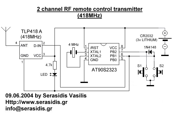
      The transmitter is constituted by AT90S2323 microcontroller and TLP434 RF transmitter module at 418MHz. I have designe the transmitter for more battery economy and safe transmition of the data.

      
          o The battery economy is made it by the use of powerdown mode of AVR. In this case the AVR goes to sleep with less than 1uA (microampere) current and wait for external interrupt on pin PB1 to awake from sleep and continue operating.


            If you press the S2 key, the logic of this pin goes to '0' (0V) and AVR awake frome the sleep mode (because PB1 is INT0) and check if pressed the S1 key. If not, the AVR take as pressed key the S2. If yes the AVR take as pressed key the S1.

            If you press the S1 key the logic of this pin and PB1 (through 1N4148) goes to '0' (0V). In this case the AVR take as pressed key the S1.


            After, calculate the checksum and transmit 4 times the same 4 byte sequence to make sure that receiver takes the data and goes to sleep mode until next interrupt on PB1.

            When the INT0 pin (PB1) of AVR goes to 0V, the transmitter TLP434A is working. If you stop press the switch S1 or S2, the TLP is stop working.

      
          o The safe transmition of the data based to transmition of 4 bytes with serial form at 2400 bps (bits per seconds). 1st and 2nd byte are for recognition of valid remote control from receiver (like ID bytes), 3rd byte is command byte. The relays status dependet by the value of this byte. Finaly, the 4th byte is the checksum of the earlier 3 bytes.


      example: if byte1=30h, byte2=35h and byte3=02h the 4th byte (chechsum) will be (byte1) XOR (byte2) XOR (byte3) = 30h XOR 35h XOR 03h = 06h.

      This method use 4 bytes x 8 bit each = 32 bit length (without start and stop bits). That is mean 1 possibility at 4.294.967.295  to receive the receiver, the same 4 bytes from some other RF device.


      This transmitter will work with all 2323 chips but better is AT90LS2323 with working voltage 2.7 - 6 volts.The microcontroller that I use is AT90S2323 with working voltage 4 - 6 volts. Its worked fine with 3v lithium battery.


            As antenna you can use ~7cm cable in to transmitter`s box.


Receiver description


Schematic of the receiver

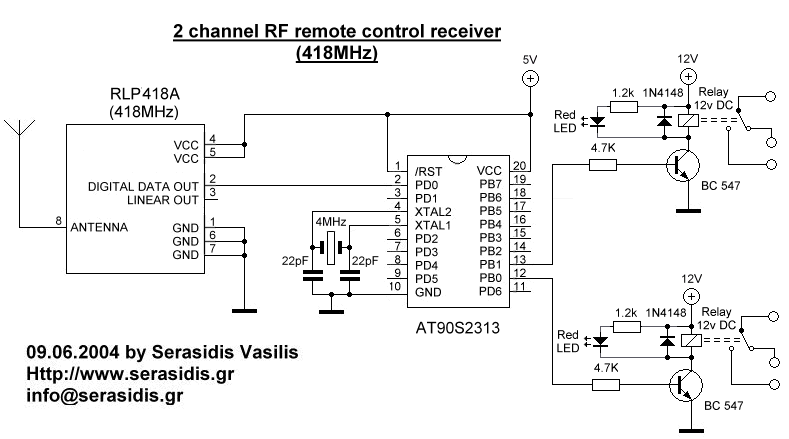
The receiver constituted by RF receiver module RLP434A at 418MHz, the microcontroller AT90S2313 and the 2 relays with can handle any electric (or electronic) device up to 10 Amps (the contacts of my relays are 10Amp at 250Volts).


The RLP434A is an RF receiver module with receipt frequency at 418MHz with ASK modulation. There are 2 outputs from this module, the digital, with levels from 0v to VCC (5 volts in our case) and the analog output. Analog output is not used. The transmitter send 4 bytes with 2400bps 4 times and the receiver RLP-434A, collect them and move them to AT90S2313 to RxD pin, PD0.

Two reasons to select AT90S2313 (20pins) instead of AT90S2343 (8pins) is because


      a.) AT90S2313 use a hardware UART adjusted at 2400bps and the hardware UART  is more stable, with smaller code, than software UART that I use in the transmitter. If some serial data arrive at the middle-time of some other routine other than receive routine,  for sure we will loose this bits of data. The hardware UART does not have this problem because have buffer for this (UDR register). This is what I mean that the hardware UART is "stable". 
      
      b.) with AT90S2313 we can drive up to 14 relays with future upgrade of the firmware, one relay to each pin.
          

As antenna you can use a cable 30 - 35cm long


The power supply
     
      The power supply of receiver
     
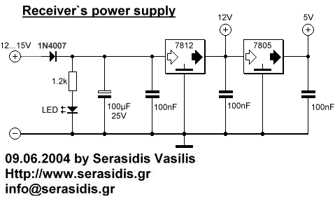
      The power supply of RF receiver constituted by 2 voltage regulator, LM7812 and LM7805. The first (12V) its only to power the 2 relays and the 2nd (5V) to power the AVR microcontroller and the RF receiver module. The LED, is voltage indicator and the 4 capacitors are to flattening  the voltage.

            
Usage of transmitter

     
      Power on the receiver and press S1 key to transmitter. You will see that relay on PB0 of receiver will arm. If you press one more time the same key, the relay will dissarm. If you press S2 key from transmitter you will see that relay on PB1 of receiver will arm. If you press one more time the same key, the relay will dissarm. Each key is for 1 relay only.
    
      I choose to drive 2 relays and not only 1 because for some application like garage door 1 relay can handle the door (open-close) and the other to turn-on or off the light of the garage.

Por: Tirso Ramírez  C.I.: 18392099
CAF
Don't Be Intimidated By Low-Power RF System Design


Don't Be Intimidated By Low-Power RF System Design

Adding wireless connectivity to any product has never been easy. However, even when a wireless solution doesn't seem to make sense, the potential exists. The cost is reasonable, and you add unexpected value and flexibility to the product. But what if you aren't a wireless engineer? Don't worry, because in many cases, the wireless chip and module companies have made such connectivity a snap.

SELECTING A TECHNOLOGY
The table lists a marvelous collection of wireless options. These technologies are all proven and readily available in chip or module form. No license is required since most operate in the unlicensed spectrum. They also operate under the rules and regulations in Part 15 of U.S. CFR 47. When considering wireless for your design, you should have a copy of Part 15 handy. You can find it at www.fcc.gov.

The table only provides the main options and enough information to get you started. For a more in-depth look, check out the organizations and trade associations associated with each standard.

Some of the wireless standards have relatively complex protocols to fit special applications. For example, Wi-Fi 802.11 is designed for local-area-network (LAN) connections and is relatively easy to interface to Ethernet. It also is the fastest, except for Ultra-Wideband (UWB) and the 60-GHz standard. It's widely available in chip or module form, but it's complex and may consume too much power.

ZigBee is great for industrial and commercial monitoring and control, and its mesh-networking option makes it a good choice if a large network of nodes must be monitored or controlled. It's a complex protocol that can handle some sophisticated operations. Its underlying base is the IEEE 802.15.4 standard, which doesn't include the mesh or other features, making it a good option for less complex projects.

If you're looking for something simple, try industrial, scientific and medical (ISM) band products using 433- or 915-MHz chips or modules. Many products require you to invent your own protocol. Some vendors supply the software tools for that task. It's a good way to go, because you can optimize the design to your needs rather than adapt to some existing overly complex protocol.

For very long-haul applications that require reliability, consider a machine-tomachine (M2M) option. These cell-phone modules use available cellular network data services like GRPS or EDGE in GSM networks (AT&T and T-Mobile) or 1xRTT and EV-DO in cdma2000 networks (Sprint and Verizon). You will need to do the interfacing yourself and sign up with a carrier or an intermediary company that lines up and administers cellular connections. Though more expensive, this option offers greater reliability and longer range.

Cypress Semiconductor's proprietary WirelessUSB option operates in the 2.4-GHz band and targets human interface devices (HIDs) like keyboards and mice. It offers a data rate of 62.5 kbits/s and has a range of 10 to 50 m.

The Z-Wave proprietary standard from Sigma Design Zensys, used in home automation, operates on 908.42 MHz in the U.S. and 868.42 MHz in Europe. It offers a range of up to about 30 m with data-rate options of 9600 bits/s or 40 kbits/s. Mesh capability is in the mix, too (see "Wireless In The Works").

BUILD VS. BUY
Deciding whether to build or buy is a crucial step when it comes to adding wireless. It's generally a matter of experience. With less experience, it's probably better to buy existing modules or boards. With solid high-frequency or RF experience, consider doing the design on your own. Almost always, you'll start with an available chip. The tricky part is the layout.

When self-designing, grab any reference designs available from your chip supplier to save time, money, and aggravation. Primary design issues will include antenna selection, impedance matching with the antenna, the transmit/receive switch, the battery or other power, and packaging. Most modules will take care of these elements.

Factoring in the testing time and cost is another essential design step. Any product you design will have to be tested to conform to the FCC Part 15 standards. Arm yourself with the right equipment, especially the spectrum analyzer, RF power meters, field strength meter, and electromagnetic interference/electromagnetic compliance (EMI/EMC) test gear with antennas and probes. An outside firm also could perform the testing, but that's expensive and takes time. Factor in some rework time if you fail the tests. Most modules are pretested, so it pretty much comes down to the packaging and interfacing with the rest of the product.

CONSIDERATIONS AND RECOMMENDATIONS
If longer range and reliability are top priorities, stay with the lower frequencies— 915 MHz is far better than 2.4 GHz, and 433 MHz is even better. This is strictly physics. The only downside is antenna size, which will be considerably greater at lower frequencies. Still, you won't be sorry when you need to transmit a few kilometers or miles. Though not impossible at 2.4 GHz, it will require higher power and the highest possible directional gain antennas.

As for data rates, think slow. Lower data rates will typically result in a more reliable link. You can gain distance by dropping the data rate. Lower data rates also survive better in high-noise environments.

Your analysis of the radiowave path is essential for a solid and reliable link. So, the first step should be to estimate your path loss. Some basic rules of thumb will give you a good approximate figure to use. Once you know your path loss, you can play around with things like transmitter power output, antenna gains, receiver sensitivity, and cable losses to zero in on hardware needs. To estimate the path loss between the transmitter and receiver, try:

dB loss = 37 dB + 20log(f) + 20log(d)

The frequency of operation (f) is in megahertz, and the range or distance (d) is in miles. Another formula is:

dB loss = 20log(4π/λ) + 20log(d)

Wavelength (λ) and range or distance are both in meters. Both formulas deliver approximately the same figures. Remember, this is free space loss without obstructions. The loss increases about 6 dB for each doubling of the distance.

If obstructions are involved, some corrective figures must be added in. Average loss figures are 3 dB for walls, 2 dB for windows, and 10 dB for exterior structure walls.

When finalizing a path loss, add the fade margin. This "fudge factor" helps ensure good link reliability under severe weather, solar events, or unusual noise and interference. As a result, transmitter power and receiver sensitivity will be sufficient to overcome these temporary conditions.

A fade margin figure is just a guess. Some conservative designers say it should be 15 dB, while others say 10 dB is acceptable. If unusual weather or other conditions aren't expected, you may get away with less, perhaps 5 dB. Add that to your path loss and adjust everything else accordingly.

Another handy formula to help estimate your needs is the Friis formula:

PR = PTGRGTλ2 /(16π2d2) PR is the received power in watts, PT is the transmit power in watts, GR is the receive antenna gain, GT is the transmit antenna gain, λ is the wavelength in meters, and d is the distance in meters. The transmit and receive gains are power ratios. This is 1.64 for a dipole or ground plane antenna. Any directional antenna like a Yagi or patch will have directional gain. It is usually given in dB, but it must be converted to a power ratio. The formula also indicates why lower frequency (longer wavelength) provides greater range (λ = 300/fMHz).

Transmitter output power, another key figure, is usually given in dBm. Some common figures are 0 dBm (1 mW), 10 dBm (10 mW), 20 dBm (100 mW), and 30 dBm (1 W). Receiver sensitivity also is usually quoted in dBm. This is the smallest signal that the receiver can resolve and demodulate. Typical figures are in the –70- to –120-dBm range.

One last thing to factor in is cable loss. In most installations, you will use coax cable to connect the transmitter and receiver to the antennas. The cable loss at UHF and microwave frequencies is surprisingly high. It can be several dB per foot at 2.4 GHz or more. So, be sure to minimize the cable length.

Also, seek out special lowerloss cable. It costs a bit more, but coax cable with a loss of less than 1 dB per foot is available if you shop around. This is especially critical when using antennas on towers where the cable run could be long. You can offset the loss with a gain antenna, but it's still optimal to minimize the length and use the best cable.

With all of this information, compute the final calculation:

Transmit power (dBm) + transmit antenna gain (dB) + receive antenna gain (dB) – path loss (dB) – cable loss (dB) – fade margin (dB)

This figure should be greater than the receiver sensitivity. Now play with all of the factors to zero in on the final specifications for everything. Two design issues remain— the antenna and its impedance matching.

The antenna requires a separate discussion beyond this article. There are many sources for antennas. A wireless module most likely will come with an antenna and/ or antenna suggestions. The most common is quarter-wave or half-wave vertical. When building an antenna into the product, the ceramic type is popular, as is a simple copper loop on the printed circuit board (PCB). Follow the manufacturer's recommendations for the best results. If it's a single-chip design, you may need to design the impedance matching network between the transceiver and the antenna. Most chip companies will offer some recommendations that deliver proven results. Otherwise, design your own standard L, T, or π LC network to do the job.

One final hint about testing: Part 15 uses field strength to indicate radiated power measured in microvolts per meter (µV/m). A field strength meter makes the measurement at specified distances. The result can be converted to watts to ensure the transmitter is within the rules. The following formula, which is a close approximation, lets you convert between power and field strength:

V2/120π ≈ PG/4πd2

where P is transmitter power in watts, G is the antenna gain, V is the field strength in µV/m, and d is the distance in meters from the transmit antenna to the field strength meter antenna. A simplified approximation at a common FCC testing distance of 3 m with a transmit antenna gain of one is P ≈ 0.3 V2.

SOME EXAMPLE PRODUCTS
FreeWave Technologies has a line of reliable, high-performance spread-spectrum and licensed radios for critical data transmissions. The high-speed MM2- HS-T (TTL interface) and MM2-HS-P (Ethernet interface) come ready to embed in OEM products like sensors, remote terminal units (RTUs), programmable logic controllers (PLCs), and robots and unmanned vehicles. They operate in the 900-MHz band and use direct-sequence spread spectrum (DSSS).

Thanks to the radios' over-the-air speed of 1.23 Mbits/s, users can send significantly more data in a shorter period of time. The MM2-HS-T is ideal for embedded applications that require high data rates, such as video and long distances (up to 60 miles). Both radios fit many industry, government, and military applications where it's necessary to transmit large amounts of data, including multiple high-resolution images and video along with data.

The MM2-HS-T measures 50.8 by 36 by 9.6 mm and weighs 14 g (Fig. 1). The MM2-HS-P shares a similarly small footprint. Both radios offer RISC-based signal demodulation with a matched filter and a gallium-arsenide (GaAs) FET RF front end incorporating multi-stage surface-acoustic-wave (SAW) filters. The combination delivers unmatched overload immunity and sensitivity.

The MM2-HS-P includes industrialgrade high-speed Ethernet that supports TCP, industrial-grade wireless security, and serial communications. Each unit can be used in a security network as a master, slave, repeater, or master/slave unit, depending on its programming. Free- Wave's proprietary spread-spectrum technology prevents detection and unauthorized access, and 256-bit AES encryption is available.

The ADF7022 and ADF7023 lowpower transceivers from Analog Devices fit well in smart-grid and other applications operating on the short-range ISM band for remote data measurement. Smart-grid technology not only measures how much power is consumed, it also determines what time and price are best to save energy, reduce costs, and increase reliability for the delivery of electricity from utility companies to consumers. RF transceivers are needed for the secure and robust transmission of this information over short distances, for storing measurement data, and for communicating with utility computers over wireless networks.

Applications for the ADF7022 and ADF7023 include industrial monitoring and control, wireless networks and telemetry systems, security systems, medical devices, and remote controls. Analog Devices' free, dowloadable ADIsimSRD Design Studio supports both devices.

One particular hot area for RF transceivers involves utilities that are building advanced metering infrastructures, including automatic meter reading, to monitor and control energy usage. Analysts expect more than 150 million smart meters to be installed worldwide. The ADF7022 and ADF7023 target these smart-grid and home/building automation applications.

The ADF7022 is a highly integrated frequency-shift-keying/Gaussian frequency- shift-keying (FSK/GFSK) transceiver designed for operation at the three iohomecontrol channels of 868.25, 868.95, and 869.85 MHz in the license-free ISM band. It fully complies with ETSI-300-200 and has enhanced digital baseband features specifically designed for the io-homecontrol wireless communications protocol.

As a result, the device can assume complex tasks typically performed by a microprocessor, such as media access, packet management/validation, and packet retrieval to and from data buffer memory. This allows the host microprocessor to remain in power-down mode. Also, it significantly lowers power consumption and eases both the computational and memory requirements of the host microprocessor.

The ADF7023 low-IF transceiver operates in the license-free ISM bands at 433, 868, and 915 MHz. It offers a low transmit- and-receive current, as well as data rates in 2FSK/GFSK up to 250 kbits/s. Its power-supply range is 1.8 to 3.6 V, and it consumes less power in both transmit and receive modes, enabling longer battery life.

Other on-chip features include an extremely low-power, 8-bit RISC communications processor; patent-pending, fully integrated image rejection scheme; a voltage-controlled oscillator (VCO); a fractional-N phase-locked loop (PLL); a 10-bit analog-to-digital converter (ADC); digital received signal-strength indication (RSSI); temperature sensors; an automatic frequency control (AFC) loop; and a battery- voltage monitor.

The CC2530 from Texas Instruments is a true system-on-a-chip solution (SoC) tailored for IEEE 802.15.4, ZigBee, Zig- Bee RF4CE, and Smart Energy applications. (RF4CE is the forthcoming wireless remote-control standard for consumer electronics equipment.) Its 64-kbyte and up versions support the new RemoTI stack for ZigBee RF4CE, which is the industry's first ZigBee RF4CE-compliant protocol stack.

Larger memory sizes will allow for on-chip, over-the-air download to support in-system reprogramming. In addition, the CC2530 combines a fully integrated, high-performance RF transceiver with an 8051 MCU, 8 kbytes of RAM, 32/64/128/256 kbytes of flash memory, and other powerful supporting features and peripherals (Fig. 3).

The TI CC430 wireless platform consists of TI radio chips. Also, the company's MSP430 16-bit embedded controller can implement the IETF standard 6LoWPAN, which is the software that enables 802.15.4 radios to carry IPv6 packets. Thus, low-power wireless devices and networks can access the Internet. Furthermore, the platform can implement Europe's Wireless MBus technology for the remote reading of gas and electric meters.

Por: Tirso Ramírez  C.I.: 18392099
CAF